Undergraduate Senior Project - GCPUD Lifting Device
Baylie Johnson
Introduction:
The rotor pole lifting device for Priest Rapids Dam was designed and analyzed by student intern Baylie Johnson of Grant County Public Utilities District. The device was manufactured by Busby International, Inc. out of Moses Lake, WA. Because this device is going to be used for lifting heavy object over people’s heads, it was necessary to do a load test to ensure safety. This load test was performed by student intern Baylie Johnson, hydro mechanics Mike Garrett and Beau Campbell. The test consisted of configuring the device, attaching the device to the crane and a pole, applying load to the device and measuring strain through a strain gage. The following report with explain the procedure in more detail, present the data taken and discuss the data.
Method/Approach
The resources needed for this test include the following
Priest Rapids Dam Powerhouse Crane
Two swivel eyes
Six shackles
10,000 pound Dynamometer
Five slings
Two horizontal lifting devices
Camera
Strain gages
Strain indicator
Switch and balance unit
Extension cord
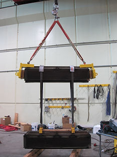
Both top plate/dovetail subassemblies were placed on either side of a rotor pole. They were then attached to a crane and lifted. There was one strain gage placed on the dovetail adapter plate to record any bending in the plate.
When the rotor pole is being tilted to or from a horizontal position the load is being carried in the dovetail. We wanted to test for this load to ensure safety. Based on a distance from the strain gage to the midpoint of dovetail contact, the strain read by the strain gage should have been 195 μs.
Procedure
1. Lower the 30 ton crane hook from the power house crane.
2. Assemble both top plates with the dovetails.
3. Insert swivel eyes into the threaded holes in the dovetail.
4. Place the dovetail/top plate combination on each side of a rotor pole laying horizontally.
5. Attach a sling to the crane hook with the loops down.
6. Connect the loops to a dynamometer with a shackle.
7. Attach another shackle to the bottom side of the dynamometer.
8. Attach two slings on the shackle on the bottom side of the dynamometer.
9. Attach a shackle to each swivel eye on the dovetails.
10. Attach one of the slings hanging from the crane to each swivel eye shackle.
11. Connect the strain gages to the reader and zero the amperage, input the correct gage factor and balance the gages to zero.
This means that the load that is contributing to the strain reading is only the difference between the dynamometer reading
and the weight of the device.
12. Raise the crane until a load of approximately 1500 pounds is applied. Record the actual dynamometer reading.
13. Record the strain gage measurement.
14. Repeat steps 12 and 13 once the rotor pole is no longer supported by the ground.
15. Attach the horizontal lifting devices (provided by GCPUD) to a second pole.
16. Attach shackles to the horizontal lifting devices.
17. Wrap two slings around the first rotor pole and attach each to a horizontal lifting device.
18. Lift the second pole until it is no longer touching the ground.
19. Record the dynamometer reading and strain measurement.
20. Lower and detach the poles.
Results
Discussion
The results of this load test were not as they were predicted. The smallest error was more than 8000%. This error most likely came from the fact that the fit between the dovetails was very poor. This caused the dovetail to tilt, as shown in the image to the right. The tilting took a lot of the stress away from the point of measurement.
Conclusion
Ultimately, this test did not provide usable results. The fit between the dovetails is so poor that the strain in the point of measurement became eight to ten thousand percent lower than predicted. However, the strain read at this location shows that it will not be a point of failure in the case of overload.
Acknowledgments
Thank you to Priest Rapids Dam hydro mechanics Beau Campbell and Mike Garrett for conducting the test.